Contouring Tools
General Tools 
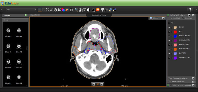
The "Contouring Tools" folder contains the following menu items: continuous (freehand) line contouring, point-to-point contouring, structure erasing, magnification within the main view window, spy-glass viewing of secondary and tertiary studies, measurement between two selected points, window and leveling, viewing of DVHs, viewing of annotations, saving contours and submitting contours for scoring, and (for mentors) loading students’ contours.
Drawing Tools 


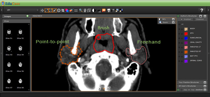
Continuous line contours can be drawn using the freehand contouring tool. Facilities are available for editing the contour by drawing a cut line from outside the contour, into the interior of the contour, and back to the outside of the contour. Similarly, a contour can be extended by drawing a line starting inside the contour, extending across the original contour boundary, and returning to the interior of the contour.
The contours are stored as polygons defined by an ordered sequence of vertices. The individual vertices of a contour can be selected by the point-to-point tool that fills the space between the vertices by a Bezier fit. The displayed vertices can be selectively moved to edit the contour. The eraser tool removes the last completed contour.
Expansion Tool (basic) 
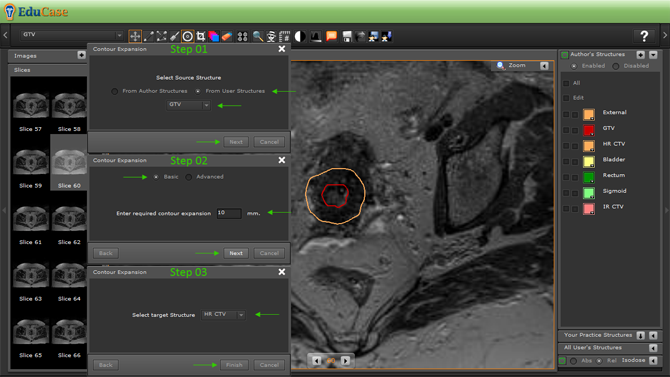
- Select source structure from either the Author or User
- Select the source structure
- Enter the required expansion in millimeter (mm)
- Enter and adjust the expansion in mm in other directions in required
- Select the target structure for expansion
Expansion Tool (advanced) 
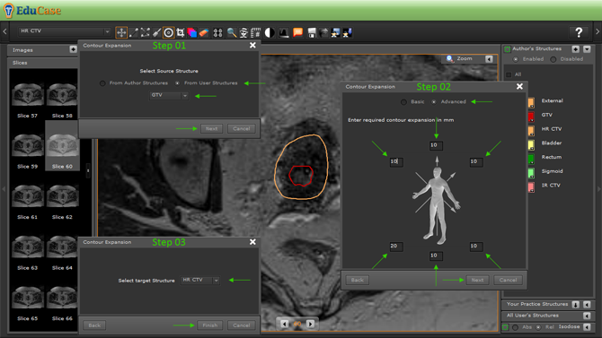
- Select source structure from either the Author or User
- Select the source structure
- Enter the required expansion in millimeter (mm)
- Enter and adjust the expansion in mm in other directions in required
- Select the target structure for expansion
Crop Tool 
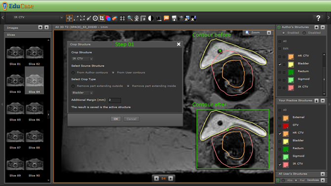
- Select source structure from either the Author or User
- Select the structure to crop “from”
- Select the crop type
- Select the target structure for the crop
Interpolation Tool 
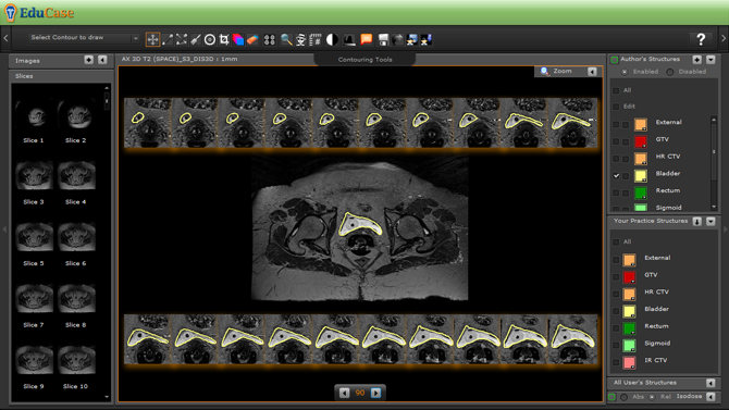
- Fills in the gaps between all drawn structures (Be sure to go through all the newly generates structures and edit/adjust if required)
Erase Tool 
- Select the structure you want to erase (if there are multiple structures on multiple slices you will need to select erasing the one slice you are on or all the slices)
- Select the structure you want to erase (if multiple iterations of the same structure are found you will need to double click it to highlight and click the delete icon again to have it removed)
Change Layout 
Change Layout - READ MORE...
Scale Tool
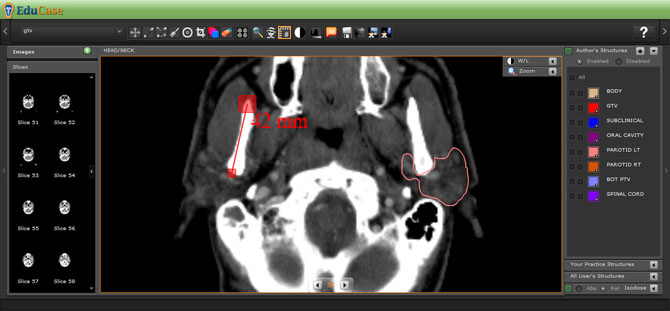
A basic measuring tool is also included in the contouring kit. It maintains its scale during the image zoom.
Window Leveling 
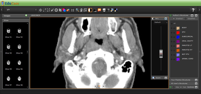
The window and level of the study can be adjusted during the contouring process to optimize the contrast of a given study for the particular tissue imaging properties of the structure under consideration. When invoked, the window/level tool is pinned to the upper right corner of the main viewing window. The upper and lower bounds of the window can be adjusted individually as well as the window center.
Image Series Controls
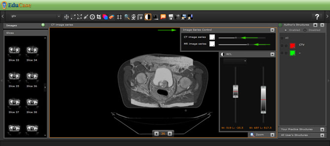
When multiple studies are downloaded, such as a planning CT and an MRI study, the studies can be viewed individually or as blended images. When viewed as blended images the overall intensity of each study can be adjusted as well as the window and level of each individual image. The user can bring out features of either study that lend to the determination of structure boundaries in the blended view. The user can then edit contours drawn initially with one study or the other and with window settings that explore the visualization of structure boundaries viewed with a particular window in one individual study modality or the other. Any number of stacked modalities can be displayed in addition to 4D gated respiratory phases.
DVH Charting Tools 
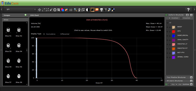
When treatment planning dose tables are uploaded with the study, the DVHs of the named structures can be displayed to illustrate advantages and disadvantages of structure boundaries in various clinical scenarios. The DVH charting can display Cumulative and Differential values when data is available.
Saving Drawn Contours 
Once the contours of a structure are completed on all axial reconstruction planes, they can be saved by the student.
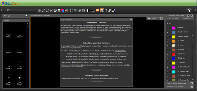
The contours can be edited further and saved repeatedly, overwriting the previously saved contour by the same name by clicking the "Save Contours" button in the save pop-up window.
Clicking the "Submit Final" button in the save pop-up window: The contour metric scoring tools operate on the areas within the boundaries of the contours (Area Domain) and on the contour lines themselves (Line Domain). The contours are scored by comparing the students’ contours with the mentor’s contours. The Dice Similarity Metric (DSC) uses counts of pixels that fall within both student and mentor contours (true positive, TP), and pixels that fall in the student contour alone (false positive, FP) or the mentor’s area alone (false negative, FN). Pixels outside each area that still fall within a rectangle that bounds both contours are counted as true negatives. The Dice Similarity Metric is computed as 2(TP)/(FP+2TP+FN) for the Area Domain. The line domain metric utilizes the distances between matched vertices in the mentor’s and student’s regularized contours. All calculations for the Area Domain and Line Domain are immediately available to students and mentors upon clicking the "Submit Final" button in the save pop-up window. READ MORE...
Loading Saved and Submitted Contours (caseowners only) 
Read "Load and Export Contours" READ MORE...
